
The ever-growing demand for longer battery life in mobile devices and energy savings in general have pushed power optimization to the top of designers’ concerns. While various techniques like multi-VT transistors and clock gating offer power savings at gate-level design, the real impact occurs at system level, where hardware and software collaborate.
A key power savings feature in modern SoC designs is the ability to dynamically deactivate design sections temporarily not in use. By enabling or disabling isolated design blocks, referred to as power islands, through hardware, firmware, or software applications, substantial energy savings can be achieved, as evidenced by hundreds of power islands found in state-of-the-art mobile devices. Notwithstanding its effectiveness, this approach poses new verification challenges, especially when validation necessitates hardware-assisted verification (HAV) to handle massive software workloads.
Functional Intent versus Power Intent
In contrast to analog design, which deals with every detail of the physical world, digital design embraces abstraction, and abstraction simplifies complexity via assumptions. At the core of the design abstraction hierarchy lies Register-Transfer Level (RTL). With RTL, functional intent, that is, design’s behavior, is captured in a hardware-description language (HDL) based on a set of rules that abstracts design functionality.
Similalrly, power intent, that is, power management strategies, is captured in a unified power format (UPF) consisting of a set of rules that abstracts the design power distribution architecture, including power domains definition and their interactions.
RTL and UPF coding reside in distinct files, merged during implementation and verification.
Power Islands Verification Challenges
In a monolithic power structure, it is reasonable to assume that if power and ground aren’t connected, no activity happens. But departing from uniform power distribution introduces complexity that can lead to functional errors.
When dealing with a design incorporating power islands, a verification plan must extend beyond verifying design logic to include power management. Merely testing functionality in static powered-up and -down states is insufficient. Transitions between on and off states present abundant opportunities for unexpected functional issues.
When an island is powered up, all registers and memories retain a defined, unambiguous logic state determined by RTL. Conversely, when an island is powered down, the circuitry’s state becomes unknown. Unknown states also arise during power transitions. Isolation cells and retention registers, as defined by UPF, prevent the corruption of design functionality caused by these indeterminate states.
A comprehensive analysis of a UPF-defined low-power design via low-level circuit simulation, while potentially very accurate, is not applicable on more than a few thousand transistors at best. Simulating software execution at RTL would be excruciatingly slow. For instance, booting an OS via an HDL simulator can take many months, making it unworkable.
A viable alternative for verifying the interaction of software with hardware as it runs on SoC embedded processors are hardware-assisted platforms. Several orders of magnitude faster than HDL simulators, HAV platforms can boot Linux in a matter of minutes instead of months. They also provide full visibility into the design-under-test (DUT) for thorough debugging.
Power Islands Validation Via Hardware-assisted Verification
Hardware-assisted verification can ensure that the logic of an entire design can still function when an island is deactivated or is transitioning from one power state to the other.
Low-power validation via HAV can identify several issues, such as:
- Bug-free IP integration
- Incorrect retention power management that leads to functional bugs
- Incorrect isolation sequencing and connection of isolation control that lead to functional bugs
- Incorrect power gating that leads to functional bugs
- Missing isolation
- Incorrect power-on reset sequencing
Unknown States in HAV
In the simulation world, the “unknown state” is represented by an “X” symbol. HAV platforms are optimized to process two-state logic and do not handle “X” states due to inefficiency in modeling a 4-state behavior with an inherently 2-state engine. During HAV every node retains either a logic “0” or “1”, which may not be known. An approach to sidestep this conundrum stems from the concept of “state corruption” affecting the island ports and core registers.
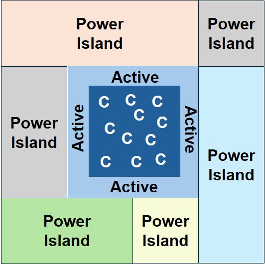
Figure 1 shows a powered down island. Since the internal core logic is assumed to be isolated from the rest of the chip, only the ports matter, hence their values are corrupted (represented by “C” in the figure). For a given application, the designer may know what the powered-down values may be, thus giving him/her control to implement the corruption.
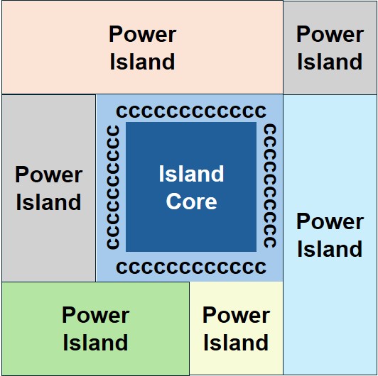
Figure 2 shows the same circuit while transitioning from one power state to the other. The assumption here is that neither the logic states of the ports, nor those of the internal registers are known. The worst case would be when the periphery is still active, propagating the results of the unknown state of the core logic. The solution here is to corrupt the core register values while leaving the ports in an active state.
This assumption empowers a verification engineer to execute a target software workload controlling all power islands iteratively multiple times using corrupted values. The process instills confidence in the correct design functionality during power up/down operations.
Modeling Corruption: Scrambling and Randomization
The concept of corruption can be modeled by randomizing the generation of logic states of either the I/O ports or the core registers via built-in hardware instrumentation running at high frequency, much faster than the design frequency. Core registers are randomized only during power state transition.
I/O Ports Randomization
In a powered-down domain all port states are pseudo-randomly assigned a “1” or a “0” at a high frequency until the domain is turned back on, unless isolation cells are placed on those ports.
Scrambling of Internal States
During power switching of an island, all internal states are pseudo-randomly assigned a “1” or a “0.”
UPF Impact on HAV Platform Capacity, Compilation, Runtime
Compilation of UPF power intent attributes onto RTL generates unique hardware structures that enable the HAV platform to verify the correct operation of the power islands. The ensuing UPF hardware instrumentation impacts three HAV deployment characteristics to varying extents, contingent upon the specific UPF attributes involved.
Capacity Impact
When compiling UPF attributes on top of RTL, the design size expands in a range of 5% to 30%. The lower range applies to designs with rather few power domains. The higher limit affects fine grained UPF/RTL designs where every instance is instrumented with UPF.
Compilation Time Impact
UPF instrumentation increases only on the front-end of compilation process, up to 10% of the total compilation time.
Runtime Speed Impact
The impact on execution speed of a UPF instrumented design can be marginal. Due to larger clock cones, higher IO cuts and potentially some optimization like constant propagation that may not fully propagate could cause a speed degradation of less than 20% of non-UPF-based design execution.
Low-Power Design Debug and Coverage
While an HAV platform is not the ideal verification engine to debug X-propagation generated by low-power corruption, it becomes indispensable to debug UPF issues in consequence of executing long test sequences and processing heavy software workloads.
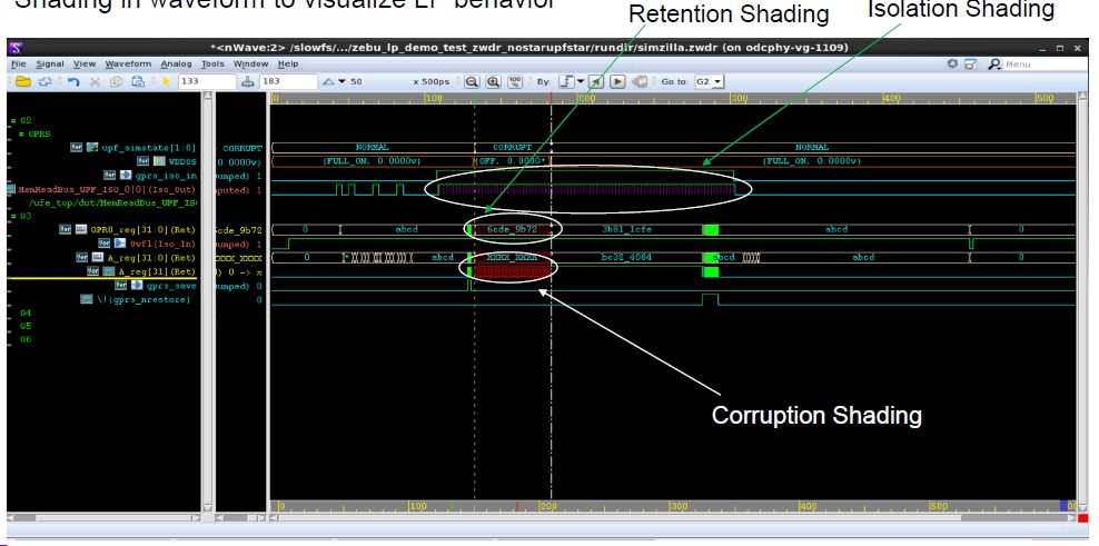
In such instances, debugging UPF instrumented designs demands enhanced capabilities on top of what is already requested for accurate RTL debug. Specific waveform notations ought to provide insight on the activity of UPF control signals and the status of UPF cells in power islands.
By adopting waveform reconstruction engines, notations to highlight powered-off, isolated, randomized or scrambled state conditions, can help verification engineers to identify:
- Wrong results in low-power boundaries (see figure 3)
- Value mismatch in HAV results (no X)
- Wrong results in power islands output even if isolated
- Wrong power domain shut-down
- Wrong retention behavior
Assertions and Coverage
As important as waveform debugging, ensuring assertions and coverage of UPF construct activity is essential to accelerate the identification of UPF incorrect behavior.
Examples of assertions include messages for power activity, warning/error messages and assertions regarding incorrect power sequences, reset/clock, and power sequence assertions.
Examples of critical coverage encompass control signals for activating power switching, isolation, and retention; power state tables, power domain simstate, and port state coverage.
UPF Operational Modes in HAVn
Although low-power SOC chips have gained popularity, few designers possess the expertise to verify power islands through HAV. To help the understanding of this emerging low-power verification methodology, a leading EDA industry conceived a series of operational modes that gradually activate UPF constructs, ranging from none to all, in incremental steps.
NOHARM UPF Mode
In NOHARM mode, UPF constructs are compiled into the DUT but remain dormant at run-time. This operational mode serves to rule out low-power instrumentation / netlist connectivity issues without the need to learn UPF functionality.
ALWAYS-ON UPF Mode
In ALWAYS-ON mode, UPF functionality is activated at runtime. Isolation and retention cells are active and will respond to corresponding isolation control and retention save/restore signals. No corruption on either power domain boundary ports or inside power down domain is performed. All power domains are active all the time for the entire HAV session, and the chip consumes full power.
FULL-WEIGHT UPF mode
In POWER-AWARE EMULATION (PAE) or FULL-WEIGHT UPF mode, all UPF attributes, like isolation, corruption, scrambling, randomization, are operational. See table I.
| RUNTIME MODES | Power Management Behavior |
| NOHARM | · Low-power cells are transparent · Power Gating, Isolation, Retention are inactive |
| ALWAYS-ON | · All power domains are turned on and no power switching happens · Isolation/Retention are active based on control/supplies · No Corruption/Scrambling |
| PAE | · Power Aware Mode · Corruption, Scrambling, Power Gating, Isolation, Retention are active |
(Source: Synopsys)
LIGHT-WEIGHT UPF Mode
Finally, LIGHT-WEGHT UPF is optimized to activate only certain UPF attributes, such as isolation and retention functionality but not corruption propagation, The benefits include lower capacity, and faster compile time and performance.
It is worth mentioning that according to user surveys, UPF isolation and retention are used by about 80% of test cases, while the remaining 20% of test cases require full PAE mode.
Table II captures the differences between FULL-WEIGHT UPF and LIGHT-WEIGHT UPF modes.
| UPF Features | PAE | LWE | ||
| Isolation | Yes | Yes – Simplified | ||
| Retention | Yes | Yes – Simplified | ||
| Corruption/Scrambling | Yes (Random/All 1/All 0) | No | ||
| Power Domain Switching | Yes | No | ||
(Source: Synopsys)
Conclusions
Proven by its ability to significantly extend smartphone battery longevity to a full day of usage through efficient power island implementation, the UPF low-power technology is rapidly gaining momentum throughout the semiconductor industry.
The widespread adoption of UPF low-power technology underscores the necessity of hardware-assisted verification to ensure comprehensive and accurate validation of modern low-power SoC designs by executing real-world software workloads. Successful UPF validation flows leverage the performance and capacity of hardware-assisted verification together with capacity efficient UPF modeling technologies and sophisticated debug technologies.
It’s a safe bet to foresee that low-power design will emerge as a ubiquitous approach in System-on-Chip development.