
Essential tools for SoC hardware/software design
Source: Electronic Products

Close to 40 years ago, the first commercial digital simulator brought to market by Comprehensive Computing Systems and Services Inc. was called TEGAS — for test generation and simulation system. Developed by a small team of experts, it operated at the gate level — analog simulators operated at the transistor level and preceded this development. It used a proprietary description language called TEGAS. It was used solely for test program generation of digital designs. Back then, design verification was still carried out via prototyping boards.
With the advent of the Computer Aided Engineering (CAE) industry in the early 1980s, the digital simulator, or logic simulation, became popular in the electronic engineering community as the main vehicle for design verification. By the end of the 1990s, it evolved into a register transfer level (RTL) simulator supporting Verilog and VHDL, the two popular hardware description languages (HDLs). It took more than a decade for the vendors, now called EDA (Electronic Design Automation, a merger of CAE and CAD) to support both languages in the same tool. Today, all three major EDA players (Synopsys, Cadence and Mentor) offer their own HDL simulators with each one roughly holding one third of the market.
A long series of enhancements over the years perfected the HDL simulator. It’s an invaluable tool now, mandatory for design verification and what-if analysis with one caveat — the design size cannot exceed about 100 million ASIC-equivalent gates. The limit is rather arbitrary and, in fact, larger designs may still simulate but the speed of execution would be excruciatingly slow.
One example
To simulate one second of real data on a 100 M ASIC-gate design running at 100 MHz a modern simulator will execute at 10 Hz – which is not an easy task at that level of design complexity – and this would take 10 M seconds to create. That is 2,778 hours or 115 days. For processing typical testbenches, one or a few milliseconds of simulation may suffice, which would cut the execution time to a day or less when run on a state-of-the-art PC configured with lots of memory. A reasonable target.
HDL simulators can run in parallel on PC farms, with each PC processing a self-contained testbench. Semiconductor companies worldwide have computing farms with tens of thousands PCs running day and night.
One hundred million cycles, though, are not enough to process embedded design software. For this task, it is necessary to execute several billion cycles in sequence since processing software is inherently a sequential process. And, PC farms loaded with HDL simulation licenses cannot come to the rescue. Software programs cannot be split in subsets and run in parallel.
How, then, is embedded software for an SoC design verified?
Enter hardware emulation
With a history of its own, hardware emulation offers another, more accurate, representation of the design before silicon availability, since it is based on an actual silicon implementation. Implemented with commercial FPGAs, starting in the late 1980s, hardware emulation became especially popular in the 1990s to verify processor and graphics designs that required long sequences of test cycles. They were marred by problems, such as a difficult and unfriendly use model, and poor reliability. The cost was high and, as single-user resource, the ROI was low. Still, a hardware emulator’s exceptional speed of execution made them essential for long sequence of processing cycles.
Using the same example as before, an emulator running at 1 MHz would take 100 seconds to execute 1 second of real time and process 100 million cycles. An emulator would boot an operating system in an hour or so. And, they were cheaper than redoing an ASIC.
Unlike the speed of execution of an HDL simulator that drops significantly as the design size increases due to cache misses and memory swapping, the performance of an emulator tends to degrade only slightly (see Fig. 1).
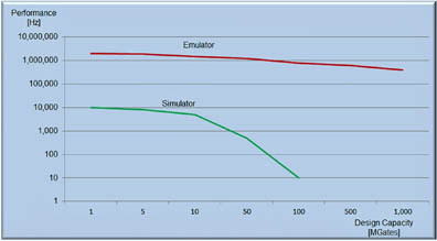
Fig. 1: Performance comparison of simulation versus emulation based on design capacity.
Limitations of the commercial FPGA-based emulators drove the introduction of custom-chip hardware emulators. Two different types have evolved: custom FPGA-based emulators, also called emulator-on-chip, offered by Mentor Graphics, and processor-based emulators promoted by Cadence Design Systems. Meanwhile, Synopsys is an advocate, with the advancements in standard FPGAs, for emulators based on the latest commercial FPGAs.
Until a decade ago, emulators were exclusively deployed in in-circuit emulation (ICE) mode as a physical test environment where the design-under-test (DUT) will ultimately reside once taped out provides the stimulus and processes the response. Because it is difficult to setup, ICE mode is less popular today, and the need for a more flexible test environment is growing. Application hardware bridges do not offer controllability/reproducibility and add to the complexity of the test environment, increasing installation time and the maintenance cost. Synthesizable test benches are a viable alternative since they can be mapped inside the emulator and executed at the maximum speed of the emulator without relying on the outside world. Unfortunately, they are difficult to develop.
Transaction-based verification or acceleration (TBV or TBX) is the most promising method in the industry, and offers two advantages. The first is the ability to write testbenches at a higher level of abstraction using an order of magnitude fewer lines of code, making it easier and less prone to errors. The second is that these test benches execute faster than conventional RTL benches, since mapping the bus-functional model (BFM) of the transactor inside the emulator achieves dramatic acceleration. Another benefit is that TBV or TBX does not require manned supervision to handle speed adapters when users swap designs or new users sign in. This mode is also good for remote access.
When to use simulation, when to use emulation
HDL simulators are good for hardware debug in the early stages of the design cycle, when the design is focused at the block level. Easy to use, quick to setup and blazingly fast to compile a design, they are exceptionally flexible to debug a hardware design. They may indeed support several design iterations per day… as long as the design size is reasonable. They become problematic at the level of several tens of million gates, which today is typical of system-level design verification. As described above, they are of no use for embedded software validation.
Conversely, hardware emulation can find almost all design bugs, whether in the hardware or in the SoC’s embedded software. They accommodate any design size, but require a long time to setup – a day at least, possibly more – and they are relatively slow to compile, compared to the simulator. It takes approximately an hour-plus to compile (see Fig. 2).
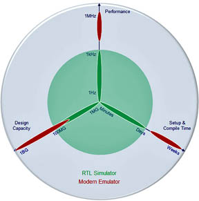
Fig. 2: Comparison of simulation versus emulation based on performance, design capacity, and setup/compile time.
Modern emulators support many concurrent users, including via remote access, thus increasing ROI.
By BY: DR. LAURO RIZZATTI, verification consultant, Rizzatti LLC, www.rizzatti.com