
Emulation performance — or its speed of execution — depends on the architecture of the emulation system and the type of deployment.
Source: EETimes
Continuing my discourse on various aspects of hardware emulators (see also DAC Trip Report: Expanding EDA’s Charter & Topical Hardware Emulation), I now wish to discuss one of the most important aspects of hardware emulation: speed of execution.
Emulation performance — or its speed of execution — depends on the architecture of the emulation system and the type of deployment. In this first column of a two-part series, I wish to discuss the type of deployment; i.e., how the design under test (DUT) and the test environment communicate with each other, managed by the run-time software. In my next column, I will elaborate on the architecture of emulation systems and how this affects performance.
The run-time software
The run-time software controls the environment that drives the DUT. It applies the stimulus, processes the response, and handles all the verification collateral essential for a thorough design verification session of an embedded system-on-chip (SoC) design, the most important being System Verilog assertions (SVAs), monitors, checkers, and functional coverage.
The run-time software embraces two different components as follows:
- The first component is tasked with bringing the hardware up to life and executing the DUT. This is the combination of the operating system running on the PC and extensive firmware loaded in the emulator. The two, in symbiosis, manage the I/O operations of the DUT mapped inside the platform and enable the user to start, stop, rewind, loop, single-step, save, and restore — all of the standard operations.
- The second component is the DUT debugger. I will address this important capability in a future post.
Deployment modes
The predecessors of the modern emulators were essentially deployed in only one operational mode called in-circuit emulation (ICE), in which the emulator was plugged into a socket on the physical target system in place of a yet-to-be-built chip so the whole system could be debugged with live data.
ICE posed its own challenges. For one, although an emulator may run up to six orders of magnitude faster than an HDL simulator, it is not fast enough to run at the same speed of a physical target system. To make things work, speed rate adapters must be introduced between the target system and the emulator. A rate adapter behaves like a buffer. It caches the signal activity from the DUT at emulation speed and sends it at real-time speed to the target system. Conversely, it captures the signal activity from the target system at full speed, caches it, and then sends it back to the DUT at emulation speed.
In the old days, the number of peripherals were few and rather simple. Today’s SoCs include many complex, high-speed interfaces, each of which would require a rate adapter to be connected to the emulator. Even when a rate adapter is available, the constant evolution of speed and complexity of individual I/O protocols has made timely rate adapter development difficult. A case in point is the evolution of Ethernet routers with an ever increasing number of ports and speeds.
An even more severe drawback of ICE is the lack of deterministic or repeatable behavior when debugging the DUT. The dependency on physical peripherals introduces a substantial degree of unpredictability of the stimulus such that a design bug may show its effect at different time stamps in two consecutive emulation sessions. Tracing a bug in this erratic environment can be a nightmare.
Another negative is that the physical devices connected to the emulator require manned supervision to connect/disconnect the adapters or to initialize the target system. All of this escalates the complexity of the setup and defeats the deployment of an emulator as a datacenter resource for remote, multi-user access.
While ICE is still in use, emulators are mainly used in other modes of operation. Gathered under the generic term of accelerated verification, there are four modes of deployment characterized by the type of testbench and the type of communication between the testbench and the DUT mapped inside the emulator; specifically:
- Cycle-based acceleration
- Transaction-based acceleration
- Embedded testbench acceleration
- Embedded software acceleration
The remainder of this column considers these modes in more detail.
Cycle-based acceleration
In cycle-based acceleration, also called co-simulation, the same testbench used in pure simulation is processed by the host workstation and a signal-level or bit-level interface connects it to the DUT loaded onto the emulator. This verification approach is the simplest and the least labor prone when moving from pure simulation to hybrid simulation/emulation, since it leverages the existing simulation testbench and removes the need for external rate adapters required in ICE. Unfortunately, the actual verification speed is severely limited by the performance of the host PC, the complexity of the testbench, and the signal density of the interface between the testbench and the DUT.
Consider that each and every transition on each and every interface signal must be transferred between the testbench and DUT at the slow speed of the testbench simulated in the workstation. Basically, the speed of the emulator is wasted waiting to carry out these signal transfers.
The speedup factor in cycle-based acceleration can be estimated by sizing the simulation time spent in processing the testbench and for executing the DUT. When the emulator replaces the simulator, for all practical purposes, the time required to execute the DUT drops to virtually zero, leaving in place the time consumed by the simulator to process the testbench. For instance, if the simulation testbench and DUT consume the same amount of time, the acceleration factor in co-simulation would be at most 2X. Unfortunately, testbenches developed for advanced SoC embedded designs may consume even more time than what’s needed for executing the DUT, leading to an acceleration factor of less than 2X.
The bottom line is, cycle-based acceleration is rarely used for design verification. One possible use, however, is to validate the DUT functionality on the emulator before moving to transaction-based acceleration.
Transaction-based acceleration
In transaction-based acceleration (TBX), also called transaction-based verification (TBV), the testbench is described at a higher level of abstraction than hardware description language (HDL) or hardware verification language (HVL). It uses an order of magnitude fewer lines of code, thereby making it easier to write and less prone to errors. Equally as important, it bypasses the need to run an HDL simulator, a cause for a major slowdown in speed of execution. Typically, the testbench is written in C++, SystemC, or SystemVerilog, and is processed in the host workstation considerably faster than conventional register transfer level (RTL) testbenches. It communicates with the DUT, loaded onto the emulator, via a transaction-level interface working at a protocol level.
A transactor consists of the front-end proxy interface, a back-end RTL bus-functional model (BFM), and a physical communications channel as illustrated below.
The anatomy of a transactor includes the front-end proxy interface, a back-end RTL BFM, and a physical communications channel
The front-end interface is typically a behavioral model that runs on the host PC and interfaces to the testbench through Direct Programming Interface (DPI) calls. It is written in C/C++, SystemC, or System Verilog. This front-end interface sends and receives high-level commands at the transactional level across the physical high-performance communication channel such as PCI Express using the Standard Co-Emulation Modeling Interface (SCEMI) standard or some variation of it.
The back-end HDL BFM runs on the emulator and interfaces with the communications channel to send and receive transactions. In the BFM, transactions are converted to a bit-level interface that interacts with the DUT.
Since the DUT’s interfaces are bit-level based, transactors convert high-level commands from the testbench into the signal-level, protocol-specific sequences required by the DUT, and translate the bit-level signals from the DUT to high-level commands expected by the testbench. The advantage is that the BFM, mapped inside the emulator, executes up to one million times faster than in co-simulation. In fact, it performs at same speed of an ICE deployment.
In addition to performance, TBX offers other advantages. It eliminates the need for rate adapters and it replaces physical interfaces with transaction-level interfaces. This avoids the unpredictability affecting DUT debugging in ICE. Further, it eludes the requirement for manned supervision to handle speed adapters when users swap designs or new users sign in. And it supports remote access from anywhere in the world. TBX also enables natural path from simulation to acceleration whereas ICE is completely disjoint verification from simulation.
It allows the DUT to connect to “virtual devices.” A virtual device is a soft model of a device that runs on the host PC. For instance, a design using an HDMI interface would be able to connect to an HDMI virtual display via an HDMI transactor. Unlike the connection to a physical monitor via an HDMI speed adapter as in ICE, the user now has full control of the transactor with the ability to run corner-cases. An example of a virtual environment is offered by VirtuaLAB from Mentor Graphics in support of its Veloce2 emulation platform.
Embedded testbench acceleration
Whenever the testbench is synthesizable — that is, it is an RTL testbench — it can be mapped onto an emulator, thereby removing all dependencies on the outside world. Needless to say, this deployment mode can take full advantage of the intrinsic performance of the emulator and achieve the highest speed of execution. Unfortunately, only few verification teams write synthesizable testbenches, limiting drastically this deployment method. It is very restrictive environment as every time you want to change the test, a complete recompile is must, which could be many hours depending upon design size.
Embedded software acceleration
The vast majority of designs fall under the category of embedded SoC designs. These include at least one microprocessor (multiple cores are becoming popular) and massive amounts of embedded software loaded into on-board memories. The software ranges from operating systems to drivers, apps, diagnostics, and even special-purpose testing programs.
As in the case of embedded testbenches, this approach is self-contained, with no connections to the outside world, thereby allowing the emulator to run at its maximum speed.
The run-time software that controls the emulator must support all of modes of execution and is tied with the operation of the design itself. It deals with any real-time issues or virtualization layers that might be required to make the hardware and processing elements available to the applications that will ultimately be visible to the system user as illustrated below.
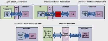
A modern emulation system supports multiple modes of execution
Last but not least, for this column, we should note that it is possible to mix modes, such as processing embedded software together with a virtual testbench driving the DUT via verification IP or even in ICE mode. Well, that’s enough for now. In my next column, I will elaborate on the architecture of emulation systems and how this affects performance. Until then, I welcome your questions and comments.
Dr. Lauro Rizzatti is a verification consultant and industry expert on hardware emulation. Previously, Dr. Rizzatti held positions in management, product marketing, technical marketing, and engineering. He can be reached at lauro@rizzatti.com.