

A quick glance in today’s design verification toolbox reveals a variety of point tools supporting the latest system-on-chip (SoC) design development. When combined and reinforced by effective verification methodologies, these tools trace even the most hard-to-find bug, whether in software or in hardware. The focus on tools and delivering a tightly woven integration between complementary tools is a strategic focus at Siemens EDA. This is illustrated by the large number of tools in the Siemens Xcelerator portfolio. The focus on integration is clearly seen with the recent announcement that the Veloce hardware-assisted verification platform has expanded to include both emulation and FPGA prototyping.
BACKGROUND ON HARDWARE EMULATORS AND FPGA PROTOTYPES
Hardware emulators and FPGA prototypes trace their origins to the breadboarding approach to test designs devised at the dawn of the electronics industry. Back then, each new design required a dedicated hard-wired breadboard, a time-consuming and expensive project. The breakthrough from the inefficient approach was triggered by the invention of the field programmable gate arrays (FPGAs). FPGAs inspired a few entrepreneurs to design protoboards populated with these new devices, making them reusable on a wide variety of designs.
From the onset, what differentiated emulators from prototypes was the number of FPGAs installed on the boards. Prototypes were built with one or a few FPGAs. Emulators were based on large arrays of FPGAs mounted on bulky boards installed in big boxes.
Not only physical dimensions set emulators apart from protoboards, but also the supporting software required to map a design under test (DUT) onto large arrays of re-configurable chips in a finite span of time.
The benefit of using emulators and prototypes is two-pronged. First, they run many times faster than simulators, increasing the productivity of the user by several folds and performing a level of testing previously unachievable. Second, they exercise the DUT with real-world stimulus instead of manually created test vectors, an error-prone and time-consuming endeavor. In the emulation world, the approach is known as in-circuit emulation (ICE) mode. The replacement of the manual stimulus creation further bolsters the productivity of the hardware platform users.
Hardware Emulation versus FPGA Prototyping
In the early days, electronics designs consisted entirely of hardware with no software content. Hardware-assisted verification tools were, and still are, a perfect fit for system validation before tape out.
Prototyping boards became popular among designers whose creations could be accommodated between one to four FPGAs. Often, prototyping boards were developed in-house, customized to specific designs.
When the number of FPGAs necessary to map a DUT testing extended beyond four, adoption of the more expensive hardware emulators called for trading the investment to acquire, operate and maintain the emulators against better testing. The conundrum tipped the scale in favor of major semiconductor companies designing the largest chips at the time, such as processors and graphics.
Continuous progress in node technology drove the creation of ever larger designs. The same progress also helped FPGA vendors develop bigger devices. The growth in size of new FPGAs could not keep up with the growth in size of ASICs and SoCs.
The situation was aggravated when design functionality migrated from hardware to embedded software. The increase in hardware complexity and adoption of embedded software opened opportunities for emulation vendors to design larger platforms based on new architectures with more features and added capabilities.
The era of hardware emulation began.
THE EVOLUTION OF THE EMULATOR
From the beginning, the FPGA-based emulator endured two shortcomings: laborious and troublesome design mapping and limited design debug. Commercial FPGAs were never intended to be deployed in vast arrays of interconnected devices because it caused routing congestion and compilation failures. Likewise, they were not designed to provide native visibility into the DUT, forcing users to compile internal probes, a necessary but ineffective workaround. Both limitations led a few pioneers to design new emulators with ad-hoc architectures.
Two approaches emerged. One architectural approach consisted of an entire emulator implemented on a chip, designed to provide 100% native visibility in the DUT instead of compiling probes. It also offered easier setup time and significantly faster compilation speed.
Another approach called custom processor-based emulator achieved the same objectives: 100% native visibility into the DUT, easier setup time, and very fast compilation speed.
The two architectures are still in use today, albeit substantially enhanced vis-à-vis the early implementations.
The commercial FPGA-based emulator did not fade away. Ameliorated over its original deficiencies, it is offered today by one of three hardware-assisted verification platform vendors.
Today’s Emulators in a Nutshell
Significant technology advances have been made including:
- Expanded capacity
- Increased execution speed
- Streamlined design setup
- Accelerated compilation process
- Augmented design debug capabilities
- Multiplied use models
- Enabled remote access, and
- Improved reliability.
Together, the enhancements significantly lowered the cost-of-ownership of a hardware emulation platform.
For example:
- Design capacity today surpasses one-billion ASIC-equivalent gates in a single box, and several billions in multi-box configurations.
- Speed of execution exceeds one megahertz (MHz), although performance enhancements have been less than dramatic.
- DUT setup requires reduced manual effort performed in days versus several months.
- Compilation speed accelerated from many thousand gates per hour to many million gates per hour.
- Simulator-like design debug with at-speed full visibility into the DUT helps verification teams in the quest to tape out bug-free DUTs.
- Broad use models, see below.
- All emulators support multiple concurrent users, either on-site or via remote access 24/7 from anywhere in the world, thus greatly lowering the cost of ownership.
- Today, reliability measured by mean-time-between-failures (MTBF) may reach many months versus less than a day when FPGA-based emulators were first introduced. Downtime is an expensive proposition for an emulation platform.
Nevertheless, not all emulators are created equal, and some perform better than others. Table 1 captures the main characteristics of the three architectures.
| CRITERIA | EMULATOR-ON-CHIP | CUSTOM PROCESSOR | CUSTOM PROCESSOR |
| Re-Prog Device | Custom-made | Custom-made | Xilinx/Itel |
| DUT Representation | Silicon Fabric | Data structure | Silicon Fabric |
| Refreshment Rate | ~4 Years | ~5 Years | Dependent on FPGA Vendor |
| DUT Completion | Fast | Fast | Slow |
| Capacity per Box | 2.5B Gates | 1.2B Gates | 2.4B Gates |
| Speed in Single Box | 1-2 MHz | 1-2 MHz | 3-5 MHz |
| DUT Debug | Full DUT Visibility | Full DUT Visibility | Limited DUT Visibility |
| Virtual Mode | Yes + Library VirtualIABs | Yes + Library of ProtocalXtors | Yes + Library of ProtocalXtors |
| ICE Mode | Yes + Library of Speed Adapters | Yes + Library of Speed Bridges | Yes – Poor Support |
Emulation Use Models
The replacement of manual stimulus with real-world stimulus in ICE mode comes with strings attached. Although several orders of magnitude faster than software-based simulators, hardware-assisted verification platforms – even FPGA prototypes running roughly 10 times faster than emulators – cannot approach physical world traffic. To work around the problem, speed adapters were inserted between the real traffic and the emulator. Consisting of first-in-first-out (FIFO) buffers, they accommodate real-world fast data transfer to the relatively slow speed of execution of hardware platforms. Speed adapters suffered a litany of drawbacks, from hardware dependencies (electrical, magnetic, radiation, environmental), to inflexibility (FIFO buffers are design-dependent and must be re-designed to support new applications), and poor reliability. Further, they require on-site manned support to switch adapters according to applications.
Traffic in the physical world is intrinsically random and unpredictable. Debugging a DUT with real-world traffic is a nightmare. Long is the list of verification engineers burned out by wasting months tracing bugs in ICE mode.
To overcome the lack of repeatable behavior and eliminate the drawbacks of speed adapters, the industry conceived of the virtualization of the test environment. A virtual testbench consists of a software model described in high-level abstraction via C++ or SystemC or SystemVerilog, generating traffic similar to that of the socket where the silicon DUT ultimately plugs in. A virtual testbench is application dependent.
The technical hurdle was the interface between the virtual testbench running on the host and the DUT executed on the hardware platform. The solution was an untimed transaction-based interface. A transactor implements a communication protocol with a proxy front-end written in C/C++ running on the host, and a bus-functional model (BFM) back-end processed in the emulator. Basically, a transactor converts high-level commands processed in the testbench into a protocol-specific bit signal sequenced in the DUT. Examples of high-level commands are Ethernet packets or video frames. By raising the level of abstraction from a signal-level interface to a transaction-based interface, the communication between the testbench and DUT got nimbler and faster, matching the full performance of the emulator.
Virtualization pushed ICE off the main stage and opened the door for the emulator to address several use models.
Today, an emulator deployed in virtual mode can perform hardware debug, hardware/software integration, and software and system validation in a variety of vertical markets from traditional networking (wired networking, Ethernet, etc.), to wireless communications and 5G, computing and storage, and transportation, specifically autonomous driving.
The virtual mode also enables power and performance analysis via the emulator.
POWER AND PERFORMANCE ANALYSIS
Two imperatives drive the design of state-of-the-art chips in leading-edge market segments: achieve the highest performance with the lowest power consumption possible.
Today’s hardware emulators can assist a verification team meet the two objectives, making them unique in this endeavor. By tracking the internal activity of the DUT, undefeated by its size and size of the workload, the emulator can generate a database to map such activity in space and time on graphical charts, easy to browse and fast to analyze.
Following a hierarchical approach, the verification team can zero in the design sections and time windows affected by high-energy consumption and quickly identify its causes.
It is acknowledged in the industry that power analysis at the register transfer level (RTL) produces results with accuracy in the ballpark of 15% compared to real silicon, whereas at the gate level the accuracy is in the ballpark of 5%. Unfortunately, analysis at the gate level happens too late in the design cycle leaving no room for effective design changes.
As an example, let’s consider performance and latency validation of a Solid-state Storage Device (SSD).
Performance/Latency Validation of SSD
While emulation is not timing accurate, it is cycle accurate, a requirement to establish how many cycles are needed to complete an operation or how many cycles are consumed between an input request and the corresponding output response. That’s what latency is all about.
As discussed previously, the ICE mode is not suitable for the task. The insertion of speed adapters between the relatively slow DUT (~1-2 MHz) and the fast target system (100MHz – 1 gigahertz) changes the speed ratios between slow design clocks and fast target system clocks. Under these conditions, no performance/latency evaluation can be accomplished. See Figure 1 below.
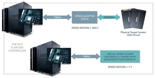
To validate performance and latency, it is necessary to virtualize the host interface since both DUT and target systems are models, and their operational frequencies can be set to any value without resorting to speed adapters. The setup preserves the clock ratio of the DUT and target system necessary to achieve a few percentage points of accuracy vis-à-vis actual silicon.
Virtual is the only solution that can validate SSD designs for hyperscale data centers with a high degree of accuracy compared to real silicon.
THE EVOLUTION OF THE FPGA PROTOTYPE
FPGA prototype technology has also evolved over time. All throughout its history, the FPGA prototype traded off debug capabilities and compilation automation in the quest for higher speed of execution than emulators.
From a board with one to four FPGAs, the prototype morphed into two classes of platforms: desktop and enterprise.
Desktop FPGA prototype platforms maintain the same basic characteristics of the early implementations, albeit now often enclosed in small boxes. While the compilation process still requires manual tuning, the performance may reach and even exceed 100MHz on a single FPGA.
Enterprise FPGA prototype platforms resemble an emulation system. Hosted in big boxes, they consist of multiple boards, stuffed with arrays of interconnected FPGAs sharing a backplane. The level of granularity, i.e., the smallest resource available to a single user, is one FPGA.
Table 2 below shows a comparison of Desktop and Enterprise FPGA Prototyping Platforms.
| CRITERIA | DESKTOP FPGA PROTOTYPE | ENTERPRISE FPGA PROTOTYPE | |
| Programmable Core | Commercial FPGA | ||
| Scalibility | Up to 8 FPGAs(on to boards) | Up to hundreds of FPGAs | |
| Granularity | Single FPGA | ||
| Board-Level Interconnect | Fully Configurable Cables | Partially Configurable Cables | |
| Backplane Interconnect | N/A | Fully Configurable Cables | |
| Rack Interconnect | N/A | Fully Configurable Cables | |
| Multi-User | No | Yes | |
| DUT Memories | Physical Models | Software Models | |
| Compilation | Front-End Share with Emulation | ||
| Development Mode | Mainly ICE | ICE, Virtual, Hybrid | |
| DUT Debug | Via Portable Insertion( Require Compilation) | ||
| Typical Task | Software + System Validation | Software + System Validation | |
| IP/Block Demo Plateform | Yes | No |
In the past few years FPGA prototyping vendors announced sharing the front-end of the compilation flow with that of the emulator to speed up the process. Similar announcements addressed DUT debug.
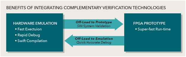
By combining prototype and emulation in virtual mode, verification engineers can quickly detect a bug via the prototype, switch to emulation running on the same DUT, and trace the bug via the emulator.
Instead of competing for the same verification job, emulation and prototyping co-exist and complement each other to accelerate the verification cycle and increase the quality of the DUT, shown in Figure 2 below.
CONCLUSIONS
Since first introduced, hardware emulators and FPGA prototypes have come a long way. Today, both are mandatory verification engines in any advanced verification toolbox. They complement each other rather than compete for the same verification tasks.
Emulators excel in hardware debug and hardware/software integration, with quick design iterations made possible by fast compilation times and through design debug. They also support performance and power analysis driven by real-world workloads. FPGA prototypes stand out in speed of execution. Joining the two in a unified flow that harnesses the strengths of each, leads to a powerful verification environment ideal for conquering the challenges posed by state-of-the-art SoC designs in AI/ML, 5G, and automotive industry segments.
A tight integration lowers the cost per verification cycle, accelerates the time to identify verification issues, optimizes the utilization of both verification platforms, and, ultimately, boosts the return on investment.